
DIY Cell Phone Detector Circuit
This was one of my first electronics projects - built it in 2020 when I was curious about RF signals and wanted to understand how passive detection actually works without a microcontroller in the loop. The circuit detects the RF burst a mobile phone emits when it communicates with a cell tower: during a call setup, SMS, or data ping.
How it actually works
Mobile phones don’t emit a constant signal. They transmit in short bursts - TDMA/GSM phones in particular fire at ~217 Hz when on a call, which is why they used to cause that characteristic buzzing in nearby speakers. This circuit exploits that.
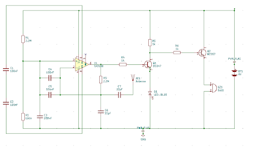
The core is a CA3130 op-amp wired as a current-to-voltage converter. Two 100nF capacitors act as a crude loop antenna - they pick up the changing electric field from nearby RF transmission and feed a tiny fluctuating current into the op-amp’s inverting input. The op-amp amplifies this into a usable voltage swing.
That swing drives an NPN BC547 transistor, which blinks an LED at the burst frequency. A PNP BC557 in the output stage drives the buzzer. The two transistor types aren’t arbitrary. The NPN handles the LED (current sinking), the PNP handles the buzzer (current sourcing from the supply rail), which keeps the load management clean without extra circuitry.
Components
| Component | Value | Qty |
|---|---|---|
| Op-Amp | CA3130 | 1 |
| Resistor | 2.2MΩ | 2 |
| Resistor | 100KΩ | 1 |
| Resistor | 1KΩ | 3 |
| Capacitor | 100nF | 4 |
| Capacitor | 22pF | 2 |
| Capacitor | 100µF | 1 |
| Transistor | BC547 (NPN) | 1 |
| Transistor | BC557 (PNP) | 1 |
| LED | any | 1 |
| Buzzer | 5V | 1 |
| Power | 9V battery | 1 |
Building it
A few things worth knowing before you breadboard this:
Antenna placement matters more than you’d expect. The 100nF caps are doing all the sensing work. Keep the leads long and unshielded, they’re literally your antenna. Tucking them flat against the board kills sensitivity.
The 2.2MΩ feedback resistors set the gain. If you’re getting false triggers from ambient noise, increase them slightly. If you’re not detecting anything, decrease them. The CA3130 has very high input impedance, so it’s sensitive to stray coupling.
CA3130 specifically. This op-amp is chosen because it can operate with inputs down to the negative rail and has MOSFET inputs. These are critical for sensing the tiny currents the capacitors generate. A standard 741 won’t work here.
Power supply noise. Add a 100µF cap across the supply rails close to the IC. Without it, the buzzer switching can inject noise back into the op-amp and cause false triggers.
What it can and can’t detect
It reliably detects GSM (2G) transmissions, the 217 Hz burst frequency falls right in the detection range and the signal is strong. 3G and 4G use different modulation schemes (WCDMA, OFDM) that don’t produce the same characteristic burst pattern, so detection is inconsistent. 5G and WiFi: don’t bother, completely different frequency ranges.
Effective range is roughly 1–1.5 meters with a well-tuned antenna, less in noisy RF environments.
What I’d do differently now
The CA3130 approach is elegant but fragile, sensitivity varies a lot with component tolerances and physical layout. A more robust version would use a dedicated RF detector IC (like the AD8313 log detector) with a proper tuned antenna, which would give you consistent detection across a wider frequency range and an actual signal strength reading instead of a binary trigger.
Still, for understanding the basics of RF detection without any digital components, it’s a good circuit to build once.